Expo-Sciences 97 - The hardware
There is a picture of the electronic circuit:
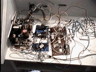
From left to right are the allimentation, the blue boards (the top one contains the decoder and the inverters the lower one contains 6 latches), after there is the rest of the latches, then the transistors.
How it works:
The computer sends data to the decoder, which sends them to the inverters. After the latches are set to on or off and stay at that value.The signal continue to the transistors who amplifies the signal power to turn on the lights .
Decoder: It takes a 4-bit code corresponding to the light we want to change the status ( on or off ) . All the outputs of the decoder are at 5V but the one selected wich is at 0V. Since I want the opposite, I need to use the inverters.
Inverter: If the input is 5V output is 0V , and vice versa.
Latches : Only one of the latch receives a signal ( 5V ) from the inverters. When this signal it checks another bit from the computer to know whether to turn on or off light. Then the latch ajust its output to that value.
Transistors : The output current of the latches is too low to turn on the lights . The transistors are used to fix that problem.
Bit: A binary signal 1 or 0, represented by 5 or 0 volts.
Technical notes:
The decoder is a 4 to 16 inputs to outputs demultiplexer. It is the 74154.
The inverters are 7404.
The latches are type D, number: 7474.
I use NPN transistors 3904.
Lights: 3V 0.230 A. It is connected to 5V, but the transistors does not produce 0.2A
Improvements between the 2 Science Fair:
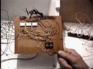
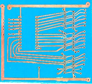
The decoder and inverter board was redone. I make my own printed circuit.
Old board:
new board:
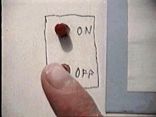
Another point: Adding buttons ON / OFF to show there is no need to go jogging after the computer to turn the lights on: